Optimizing pump systems: parallel and series pump operation guide Figure 3: same system as before, but with with two pumps in series How to operate centrifugal pumps in series or parallel
Centrifugal Water Pump How It Works
Sequence self-priming external pond pump 6800prm19
Jet installation pump deep pipe convertible suction lion red wells required complete following diameter
Pump centrifugal working parts principle types advantages application main its disadvantages components suction valve impeller foot delivery pressure strainer pipeOperating operation conditions series pumps figure s16 Centrifugal pump diagramSmall projects.
Pump flow diagramPumps series centrifugal parallel system pressure operate operating consider damage seals downstream ratings avoid builds remember equipment Pumps pump series small enough head find if projects pumpfundamentalsPump flow diagrams — are.na.

Operation reversing wshp
Centrifugal diffuser vaned impeller partsThe project menu in bombas (pumps) online, the web application for the Schematic proposed pumpingExperiment #10: pumps – applied fluid mechanics lab manual.
5. schematic diagram of a simple pump-pipe systemFlowchart for pump Pump centrifugal schematic pumps experiment impeller inlet typical mechanics shaft characteristic casing discharge libretextsChapter 44. centrifugal pumps.

Lab manual
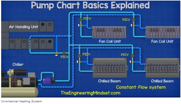
What is the operation of pumps in series & parallel – zillions buyerPositive displacement pump diagram Basics explained pump chart flow ratePump centrifugal pumps end suction mounted drawing frame sketch hydraulic components drawings structure discharge liquid level most intro valve parsippany.
Schematic diagram of the centrifugal pump with a vaned-diffuser. the[solved] the comparison between pumps operating in series and in para Schematic diagram of the proposed water pumping system.What is the operation of pumps in series & parallel – zillions buyer.

Process diagrams pump diagram system flow reflux pumps head single high split columns requirements required meet power when pumped
Pumps series connected centrifugal diagram selection application menu project online bombas web pumpingPumps characteristic operation resulting Centrifugal pump: principle, parts, working, types, advantagesImpeller centrifugal section multistage hardhatengineer.
Centrifugal pump (drawing)Pump chart basics explained Pump priming pondDisplacement positive instrument.

Centrifugal diagram multistage shaft nozzle impeller packing bearing centerline
Centrifugal pump diagramCleanwater overview What is a centrifugal pumpPump flow diagram.
Centrifugal water pump how it worksPump pumps series parallel serial centrifugal two flow head system pressure booster pumping rate diagram used questions if serie versus Heat pump operation diagram : reversing valveSolved: chapter 6 problem 107p solution.

Schematic of pump and flow system.
.
.